PipelineC Experiments - Part 1
So… this is the begining of my journey learning and experimenting with PipelineC a tool that “translates” C code into FPGA HDL code (VHDL).
I started by downloading and installing the tool along with the OSS-Cad-Suite and cocotb. My first simulations were using Verilator but I changed to GHDL + cocoTB for a better debug output.
Running the ./examples/verilator/blink.c example yields:
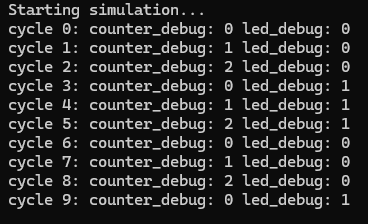
Verilator debug output.
Wanting something more complex and SDR / DSP related I started writing one NCO (Numerically Controlled Oscillator) which is the software version of a VCO (Voltage Controlled Oscillator) and the base for the DDS (Direct Digital Synthesis).
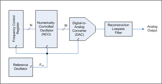
Direct Digital Synthesizer block diagram from Wikipedia.
They work by using one accumulator that holds the phase information, this gets incremented every time we want another a new output by the control word ammount. The outputs can be derived from doing on the fly calculation of the sine and cosine, complex exponentiation or by using one LUT (lookup table) with the values of the function you want to generate.
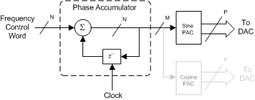
Numerically Controlled Oscillaltor block fiagram from Wikipedia
Something “special” about this table is that instead of usin a sine table like most NCO’s do I opted for one cosine table with pi/2 (90 degrees) shift for the sine output. This uses less memory than adding 2 separated tables (not sure if that is even done anyway…) and uses more “computation” by adding the offset when looking up for a value on the table.
The first implementation used 8bit fixed point unsigned integers uint8_t for the control word (vco equivalent of control voltage, that changes the output frequency), phase accumulator, cosine table and output, after migrating to GHDL + cocoTb simulation the NCO was rewritten using 16bit fixed point integers uint16_t for the output and cosine table entries.
Here is one snippet of the Code for the latest NCO version, you can find the full code here.
#include "uintN_t.h"  // uintN_t types for any N
#include "intN_t.h" // intN_t types for any N

// Generate top level debug ports with associated pipelinec_verilator.h
#include "debug_port.h"
DEBUG_OUTPUT_DECL(uint8_t, phase_debug)
DEBUG_OUTPUT_DECL(int16_t, cos_debug)
DEBUG_OUTPUT_DECL(int16_t, sin_debug)

// complex int16_t struct
typedef struct ci16{
  int16_t real; // I component (real part)
  int16_t imag;  // Q component (imaginary part)
} ci16;
On this snippet I include the headers contaning uint8_t and int16_t types and the debugging ports for GHDL/cocoTb simulation. I also create the ci16 struct / type wich represents 2 16bit fixed point integers mapped in the range (-1.0, 1.0).
On the next snippet we have the sttruct that holds the NCO state and the cosine table below it with variables defining its size and sine offset.
// nco state struct
typedef struct nco_state{
  ci16 m_out; // output iq
  uint8_t m_phase; // phase accumulator
  uint8_t m_control; // control word
} nco_state;

// NCO cosine table
#define TABLESIZE 256
#define OFFSET TABLESIZE/4
int16_t table[TABLESIZE] = {32767... -32764... 32767};
Finally we have the next_nco function wich is responsible for updating the phase and generating a new complex output. Right below it the global nco state is created and the main function is declared.
nco_state next_nco(nco_state state){
  state.m_phase += state.m_control;
  state.m_out.real = table[state.m_phase];
  state.m_out.imag = table[state.m_phase+OFFSET % TABLESIZE];
  return state;
}

// Output iq (sine & cosine)
nco_state state;

#pragma MAIN main
ci16 main()
{
  // Connect to cocotb debug wires
  cos_debug = state.m_out.real;
  sin_debug = state.m_out.imag;
  phase_debug = state.m_phase;

  state.m_control = 8;
  state = next_nco(state);
  return state.m_out;
}
The main() function gets converted into a pipeline that will be executed on the FPGA device (or simulator), inside there we have debug wires to monitor the nco state and the line state.m_control = 8 sets the NCO control word increment to 8. This means every 1 cycle the nco phase will increase by 256/8 = 32 entries, which is equivalent to clock/32Hz.
Here is one screenshot of the NCO debug wires plotted in Python with Matplotlib:
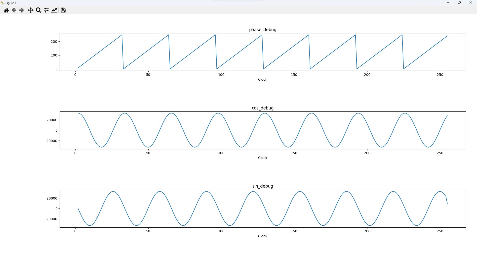
Plot of debug wires, 256 cycles simulation.
I guess that’s it for today… On my next blog posts I will talk about the FM modulator / Demodulator and FIR Filter simulations that I made with PipelineC. Bye! See you on the next post…
References
Direct digital synthesis - Wikipedia
Numerically controlled oscillator - Wikipedia
Building a Numerically Controlled Oscillator - ZipCpu
What’s Your IQ – About Quadrature Signals - Tektronix Blog